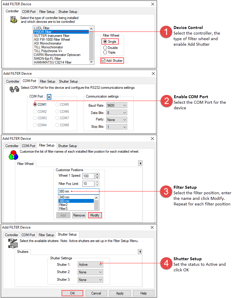
Motorized Filter and Wavelength control devices are supported from a number of manufacturers. Multiple devices can be installed and used in conjunction, allowing simultaneous control of excitation and emission wavelengths. With the added control of capture and shutters devices it is possible to completely change the image acquisition illumination environment for successive images. Combinations of Filter and Shutter positions are configured and selected in the Filter Setup, accessed from the Device Tab on the side panel. Use the Following steps to add a Filter Device to a Profile and test it:
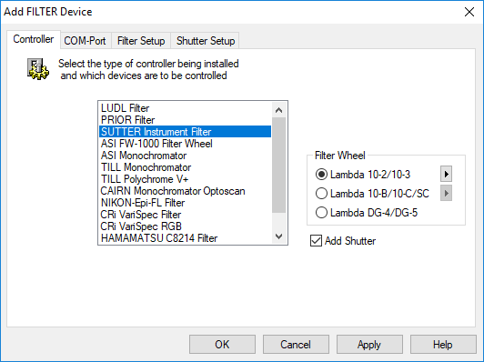
Use this menu to select the Manufacturer for the Device Controller being added. This determines the interface and communications protocol that is used to communicate with and control the device.

As the filter type is selected, various options will become available to corresponding to hardware options for that device. Configure all settings to match the features on the device you wish to control. Some filter devices include shutters and some allow shutters to be added as an option. A shutter tab will become visible automatically in the former case but appear in the latter case only if the appropriate options are selected (such as "Add Shutter" in the above example).
Note: Specifying the wrong controller type may cause problems when sending commands that are not correctly supported. In such a case the controller and possibly the host computer system may need to be powered off and reset.
Select the COM port for RS-232 communications. The Baud rate and other communications parameters must be correctly set to achieve proper control. Check the manufacturer’s documentation and specifications first. The default values are likely to be correct, but may not be in all cases.
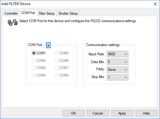
Using the button next to the "COM Port" buttons group label will scan for available COM-Ports. If an existing COM port is grayed, it is either already in use by another device, or disabled in the system BIOS.
Note: In some cases, the COM port may be shared with another device (filter, shutter, stage, etc.) that uses the same controller or may be in use by a different device.
Avoid selecting a COM port to which a modem or other communications device is attached, as this may cause serious system problems when communication is attempted.
The Controller Properties menu allows the physically installed filters to be added to the software control. There may be one or more filter devices listed in this display. The Filter Setup tab displays the available features of the selected device.
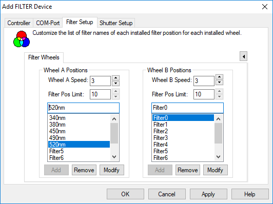
The Filter Pos Limit setting shows the maximum number of filter positions that the controller can address. In some cases this can be modified to allow more or less filter positions in the list. Use the Add, Remove and Modify buttons to create filter names in the list. To modify an item, select it and click Modify to change the name.
Note: For some devices a single controller can accommodate multiple Filter control cards providing an increased number of devices that can be integrated using one COM Port. For these devices additional items are displayed. Select the Board Addresses manually (S1, S2, etc.), or use the Auto button to detect the Board addresses in use.
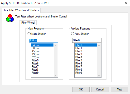
Once Filter communication has been configured in the Profile, press Apply to verify your device in the Apply Dialog. The Test button will activate each filter in the list to allow you to verify that the installed filters match the filter configuration.
Note: Wavelength calibration is performed in the Monochromator pane in the Device pane.
Note: Prior to adding the TILL Polychrome V+ to a profile, install the TILL driver (included with the device) and put the TILLPolychrome.dll in the HCImage directory (C:\Program Files\HCImage).
